¶ MEPSizer
The MEPSizer application is part of the Revit add-in A400-RTools. The application allows users to calculate the pipe or duct diameter while sketching the network,
increasing productivity.
The calculation standards for hydraulic systems follow the Portuguese legislation Diário da República nº 23/95 de 23 de Agosto and aeraulic systems
calculation follow ASHRAE standards and
guidelines.
¶ Hydraulic Systems

Water Supply Network [Published]
Wastewater Drainage System [Published]
Stormwater Drainage System [In Development]
¶ Aeraulic Systems

HVAC Systems [In Development]
¶ Setup
The application is installed via the A400-RTools setup, which can be downloaded from the A400-Soft.
¶ How it works
¶ Automatic initial configuration
The first time it's executed in a model, the application creates three
shared parameters:
- MEPSizer_ConnectedTo - Id: 386fa8ee-1b24-4ad6-9629-69cfa0cfefcf
- MEPSizer_EquipmentList - Id: 6f98af84-0783-4d2b-8415-65abc89a481
- MEPSizer_Identification - Id: 9bf81dbf-9460-4f6b-b7ba-467153028cf5
This parameters are associated with the following categories:
- Pipes
- Pipe Fittings
- Pipe Accessories
- Plumbing Fixtures
¶ Hydraulic Networks
¶ Water Supply Network
-
¶ Download the test model
Example (Revit 2023)
-
¶ Initial configuration
The two parameters that represent the inlet flow and associated localized pressure loss in the Plumbing Fixtures category must be defined.
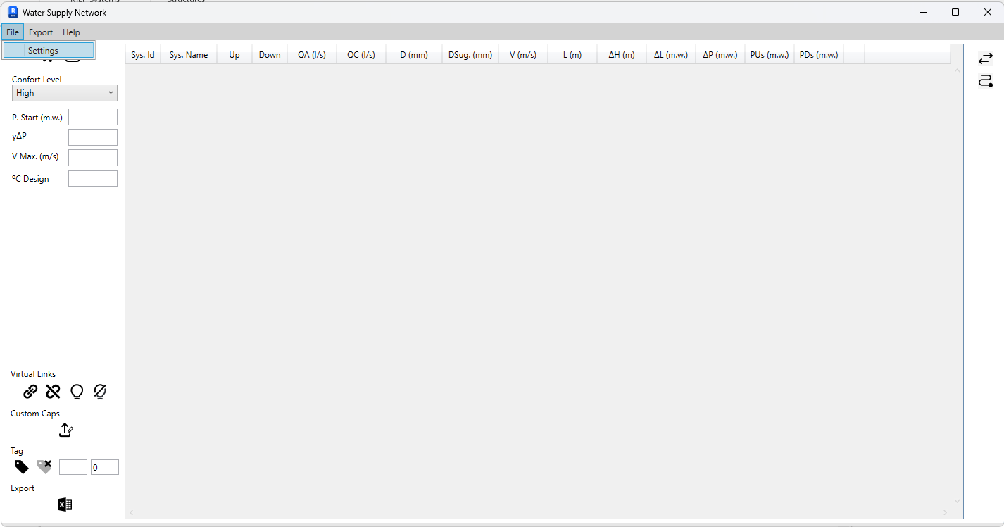
Defining the calculation parameters: File -> Settings

Parameters used in the sample model. Parameters are saved upon closing the window -
¶ Virtual Connections
- How it works
Virtual connections are used when it is necessary to connect two elements that are not connected in model.
These can only be made between elements from the categories Pipe Fittings, Pipe Accessories, and Plumbing Fixtures.- How to virtually connect two elements?
Select the elements to be connected and click the button indicated below. A connection between all selected elements is created.
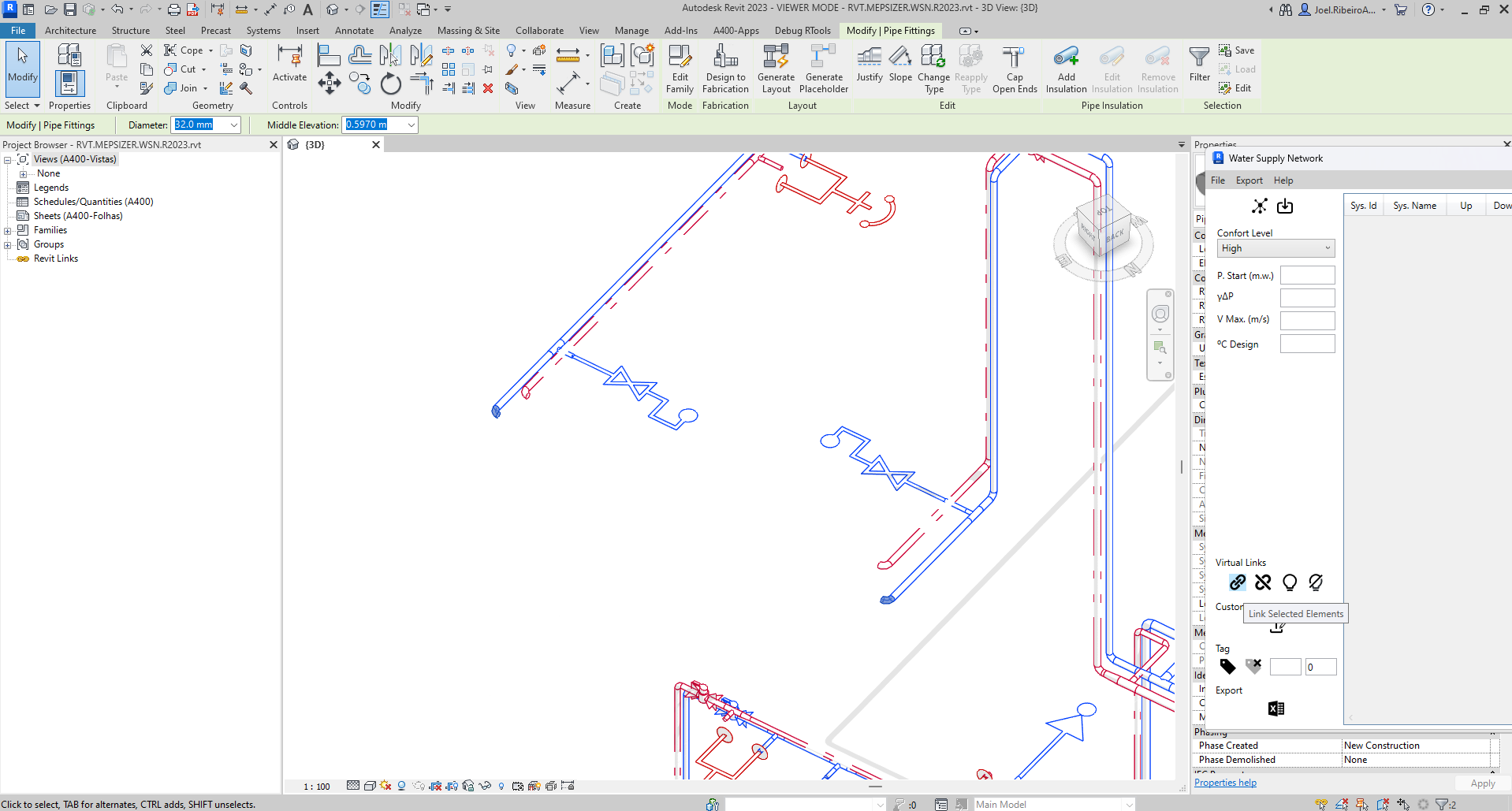
Select the elements -> Link selected elements
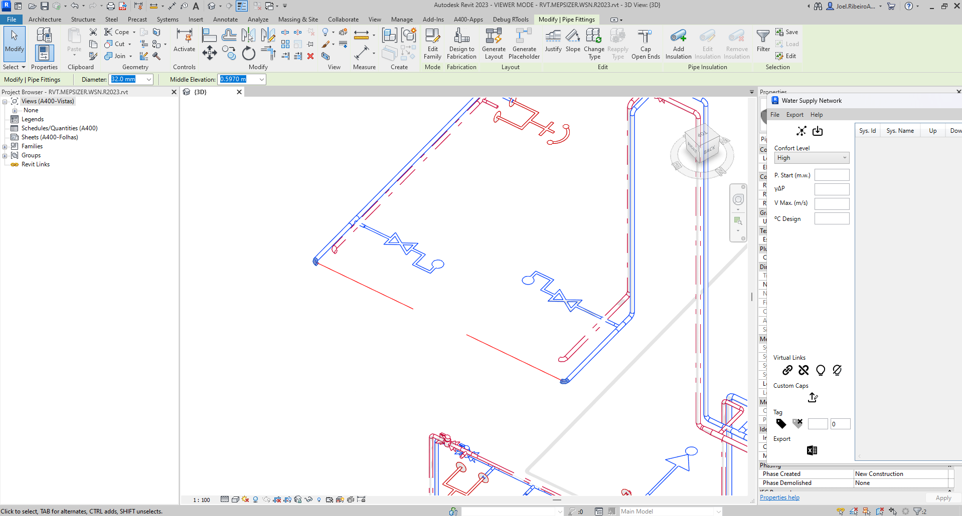
A representative line of the connection is created, which can be deleted if needed. It serves only for user identification

The MEPSizer_ConnectedTo parameter will be populated with the Id of the element to which the selected element is connected- Virtual connections controls

- Create a link between selected elements
- Remove links from selected elements
- View links of selected elements
- Hide links
-
¶ Custom Caps
If the network is not fully modeled, it is possible to introduce custom caps that represent a group of equipment. The equipment options are limited to those already loaded into the model from the Plumbing Fixtures category.
To customize a cap, first select the element and click the button as indicated below.
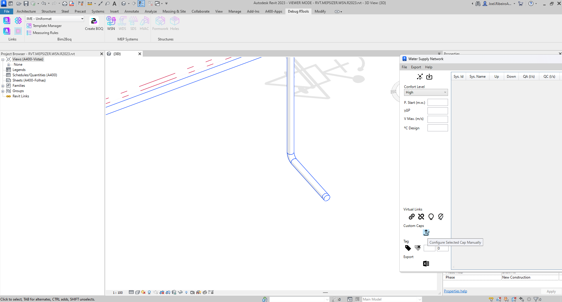
Configure selected cap manually.
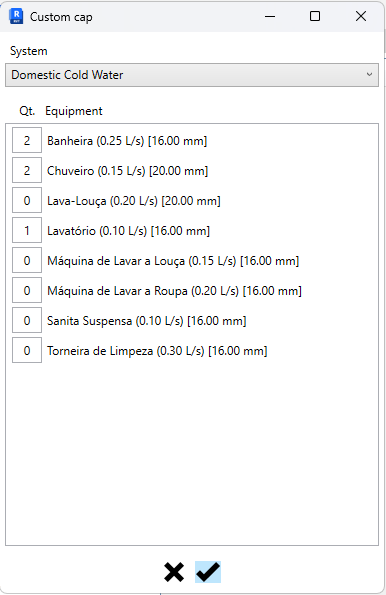
The available equipment is organized by system. Select the system and specify the quantity of the desired equipment
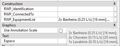
The MEPSizer_EquipmentList parameter will be populated with the selected equipment listEach equipment type is presented in the following format:
{Qt}x {Type} ({Flow} {Unit}) [{Connector Diameter} mm];The Connector Diameter is respected as the minimum pipe diameter.
To remove the cap, simply set the equipment quantities to 0 or clear the parameter value. -
¶ Network Sizing
After the initial configurations and network modeling, input parameters must be defined for the calculation:

- Comfort level
- Network inlet pressure
- Continuous loss coefficient (a conservative way to account for localized losses associated with network accessories)
- Maximum allowable velocity
- Water temperature
To start the precess, select the elements to resizing and import the results:
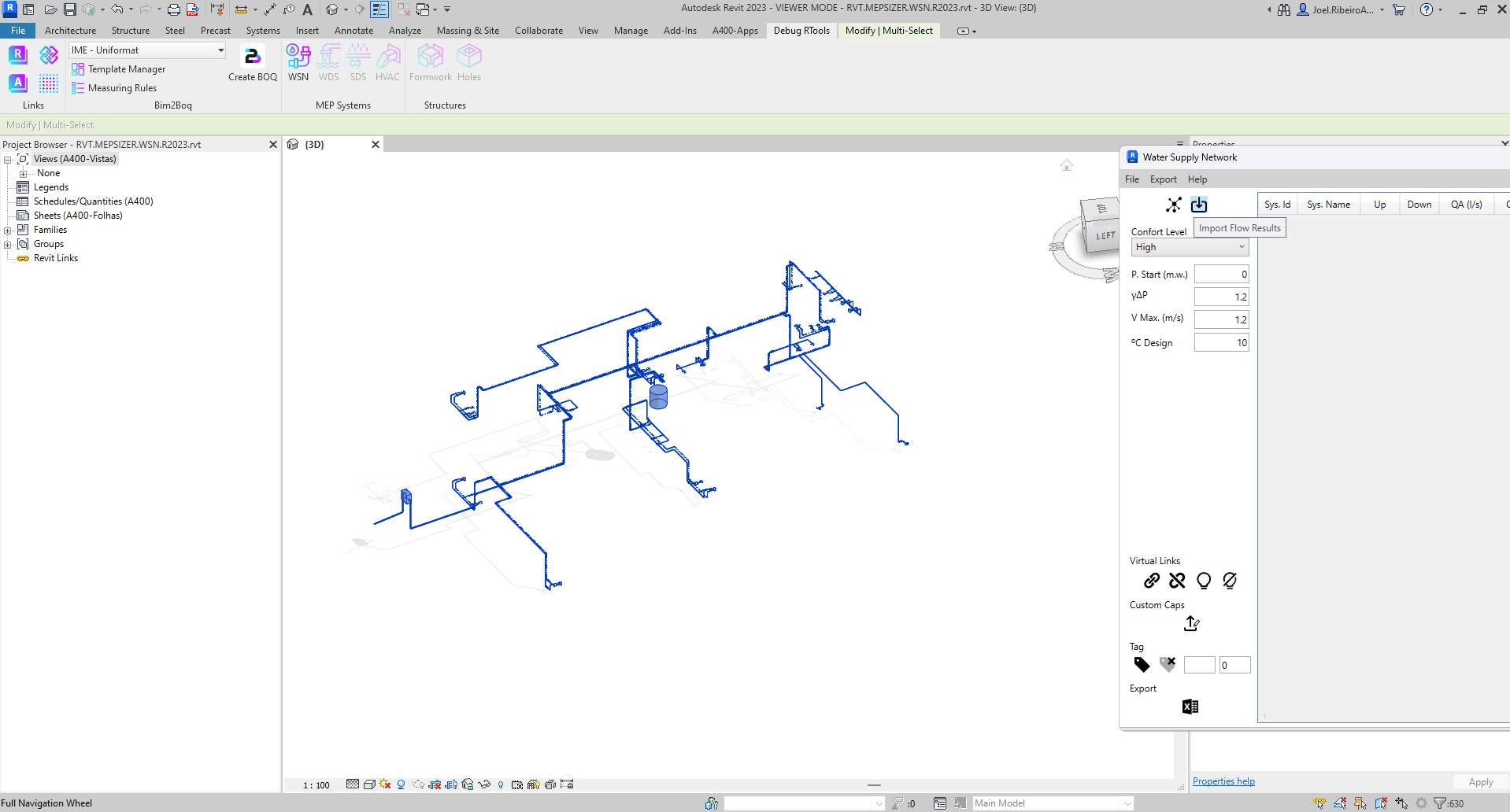
Import the resultsAlso, it is possible to select the elements that are in same network of the selected pipe.

- Select connected elements
- Import the results
The results are displayed in a table, which through the same, is possible to correct and resize the diameters that doesnt complie with the calculations criterias.
The application suggests the diameter (the available diameters are provided by the revit model) and the user can change or accept the same.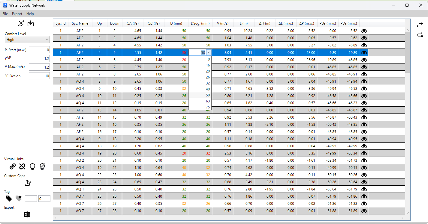
Choose the diameter for each pipe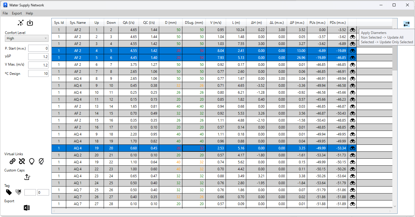
Apply selected diameterWith the results calculated, it's possible to highlight the critical path to the equipment with less water pressure.

- Apply the diameter to the respective pipes
- Select the critical path
Before export the results, the nodes can be tagged with a custom prefix.

- Tag elements with prefix F, starting from number 1
- Remove tags from selected elements
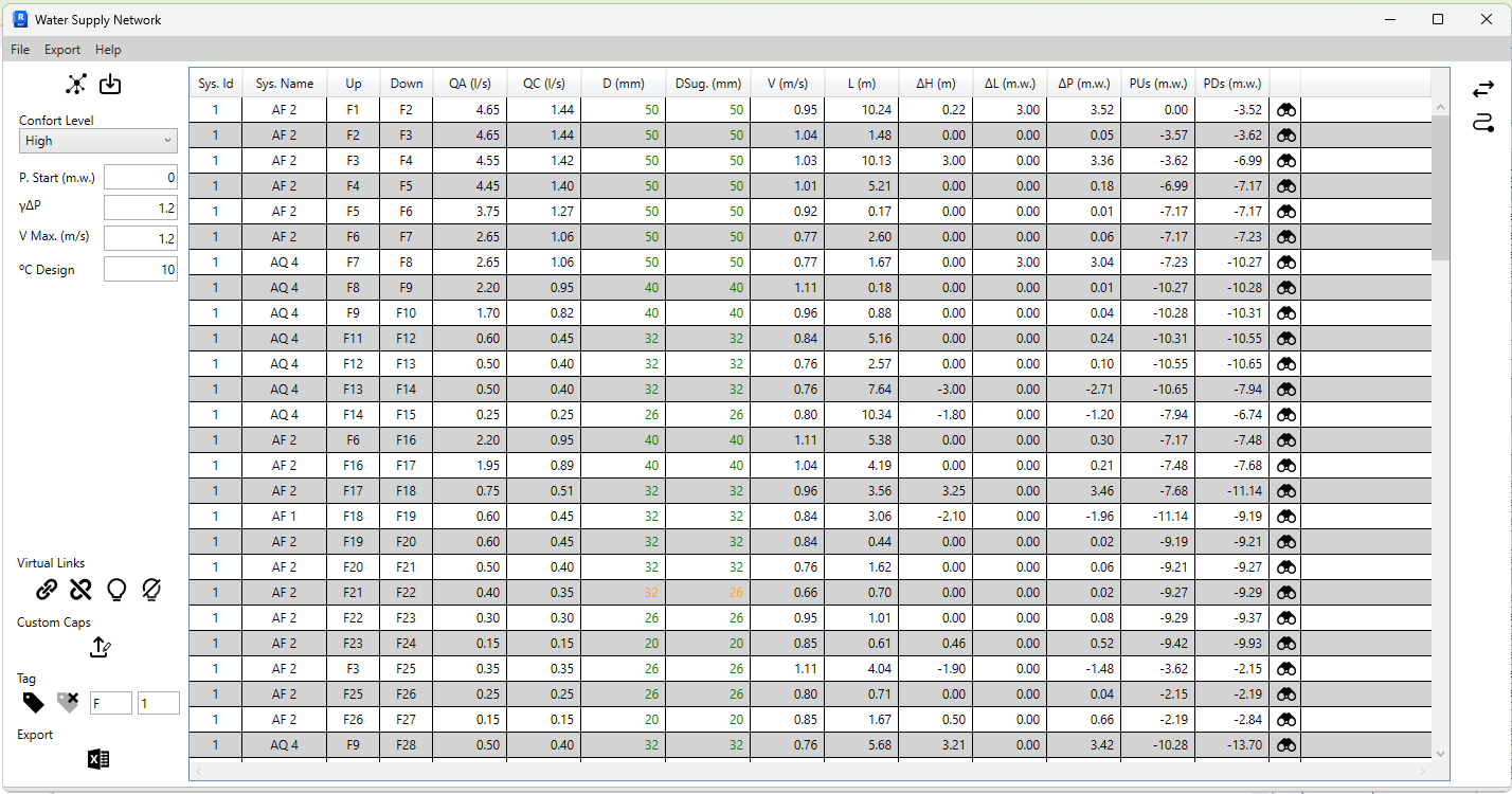
Tagged elements
MEPSizer_Identification parameter filled with the tag -
¶ Export to Excel
To export to Excel, it is necessary to define which columns are associated with the calculation parameters that the application exports.
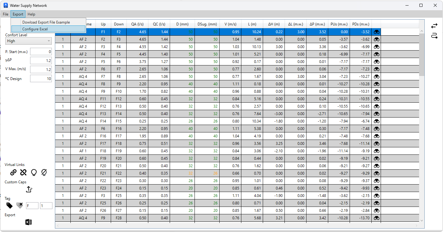
Export configuration: Export -> Configure Excel
Default values correspond to the example templateAfter configuring, open the Excel file where the results will be exported, and select the row from which the results will be exported. This allows exporting parts of the network to the same file.
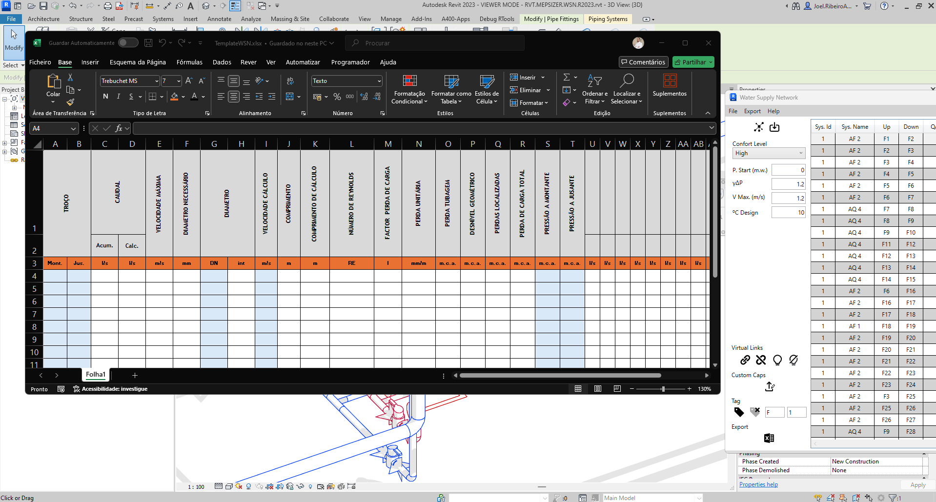
Export process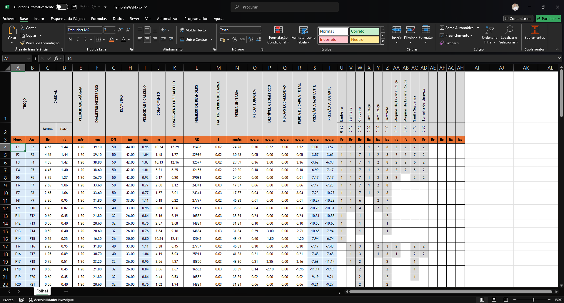
RExported results - PTIf another template is desired, simply keep that file open, and the application will export to the active file.
-
¶ Future Developments
- Flow conversion curve for equipment.
¶ Wastewater Drainage System
[IN DEVELOPMENT]
¶ Stormwater Drainage Network
Under development
¶ Aeraulic Systems
Under development